Why Use a Flexible Feeder?
Flexible feeding is the logical alternative to belt, bin or bowl feeding for automated assembly or packaging.
Belt feeding utilizes a motorized conveyor belt to move product through a packing cell. The product can be on the belt in any orientation, its position and orientation is evaluated by a machine vision system with position coordinates transferred to a robot controller. From there a robot picks the product from the belt and places it into a package or work-holding fixture for further processing.
Bin feeding using 3D vision to locate good candidate parts and guide a robot to grip and pick the parts is interesting but very problematic. Fast and dependable vision to identify and locate parts is still quite challenging. Robot gripping from an infinite set of poses, requiring different approach angles for the robot arm and gripper are also very challenging, especially at full production speed of 20-45 parts per minute.
Bowl feeding is best suited for mechanical “hard” automation where a high volume of a single product are oriented and presented to fixed automation and assembly machinery. Bowl feeders must be specifically designed for each part and cannot easily be converted to feed a different part. Hence, in high mix production environments it is common to have hundreds of different types of feeder bowls, each with its own qualities and maintenance requirements.
Why use a Flex Feeder?
Flex feeding addresses the shortcomings of belt, bin and bowl feeding for high mix, relatively low volume (less than 5000 parts per day) production environments that utilize robots for assembly
- Each feeder size will run a wide range of part shapes and sizes, with the longest dimension approximately 1/25th to 1/5 the width of the feeder
- Flexible feeders are designed to orient and separate parts on the “feed deck” so they are easy for a robot to pick
- Flexible feeders are capable of flipping parts so that the side up facing a vision system can be evaluated for its orientation
- Flexible feeders can mechanically and automatically dispense bulk parts onto the feed deck, can move the parts forward to optimize the picking region on the deck (the highest number of good candidates possible) and can also be programmed to reverse the parts out of the back of the feeder into a bin so that the parts to run can be changed over automatically
- Flexible feeder systems, which include the vision system, robot and gripping components, have a maximum pick and place full cycle time of about 1.5 seconds or 45ppm. This is not brand dependent, but is about the physics of picking and placing a part accurately over the reach and radius of the robot arm. If the feeder and vision system are selected properly, neither will be a constraint to cycle time. Vision tasks can be conducted while the arm is placing the component, in less than 1 second; feeding (and part settling) tasks can take 5-7 seconds, but if the FOV accommodates 20 or more parts, it should not add much to the overall system cycle time over 1 minute.
Machine Vision
Flexible feeders rely on machine vision to locate a part on the feed deck and communicate the position and orientation back to the robot controller. A well designed vision program will identify parts that are not overlapping and have sufficient separation to be effectively picked without error. A wide range of machine vision resolutions, lens, fixturing and lighting options are available to optimize the part location and orientation. Vision system memory and the ability to call multiple part programs will allow many different types of parts to be run on the same feeder.
- Resolution should be sufficient to locate the part with +/- 1% accuracy across the entire Field of View (FOV) which can be 100X or more the area of the part profile
- Resolution should be sufficient to identify any special markings if “right-side up” is required
- Color is also available to identify features on a part, if needed
- Lighting: what is the light source, under the feed deck for back-lighting parts (where silhouette is all that is necessary to ID and locate the part) or top-lighting, for parts that have variation on one side or the other that must be identified before picking. What color or wavelength of light is best for the part and environment: White, Red, or Infrared?
- What communications interfaces on the vision sensor are available? The faster the better. The latest “GigE” standard allows for high speed communications so it does not become a bottleneck in system performance
Engineered Feed Deck
The flexible feeding deck is available in a wide range of materials for the best interaction and presentation for the desired part to be run. Here are some of the options available for feed decks:
- The materials can be opaque for top-lighting or translucent to allow back-lighting through the feed deck
- Feed deck material colors can be white, brown, blue, black and in most cases (except black) translucent for back-lighting
- Material properties can be a wide variety of plastics to best match the part and environment: POM (Delrin), PVC, PTFE, ABS-ESD and others
- If parts are prone to rolling which reduces cycle time and increases the chance of picking error, the deck can be machined with grooves, bumps or even pockets of varying sizes to hold parts in place for picking
Integration of Feeder, Vision and Robot
The final consideration for flexible feeding is the integration of all parts into a well designed system.
- Which is the best size feeder for the parts to pick? Generally, the larger the better so that more parts are available as good candidates after every dispensing cycle. This will minimize the dispensing time as a percent of total system cycle time allowing more picks per minute
- How effective is the mechanical feeding process for a given part? An evaluation on each part should be conducted so designers can determine potential cycle time (ideally using robot simulations) and to determine how the part can be gripped repeatably. Certain materials and shapes present special problems for flexible feeding that can be creatively solved with feed deck material selection and “structuring”
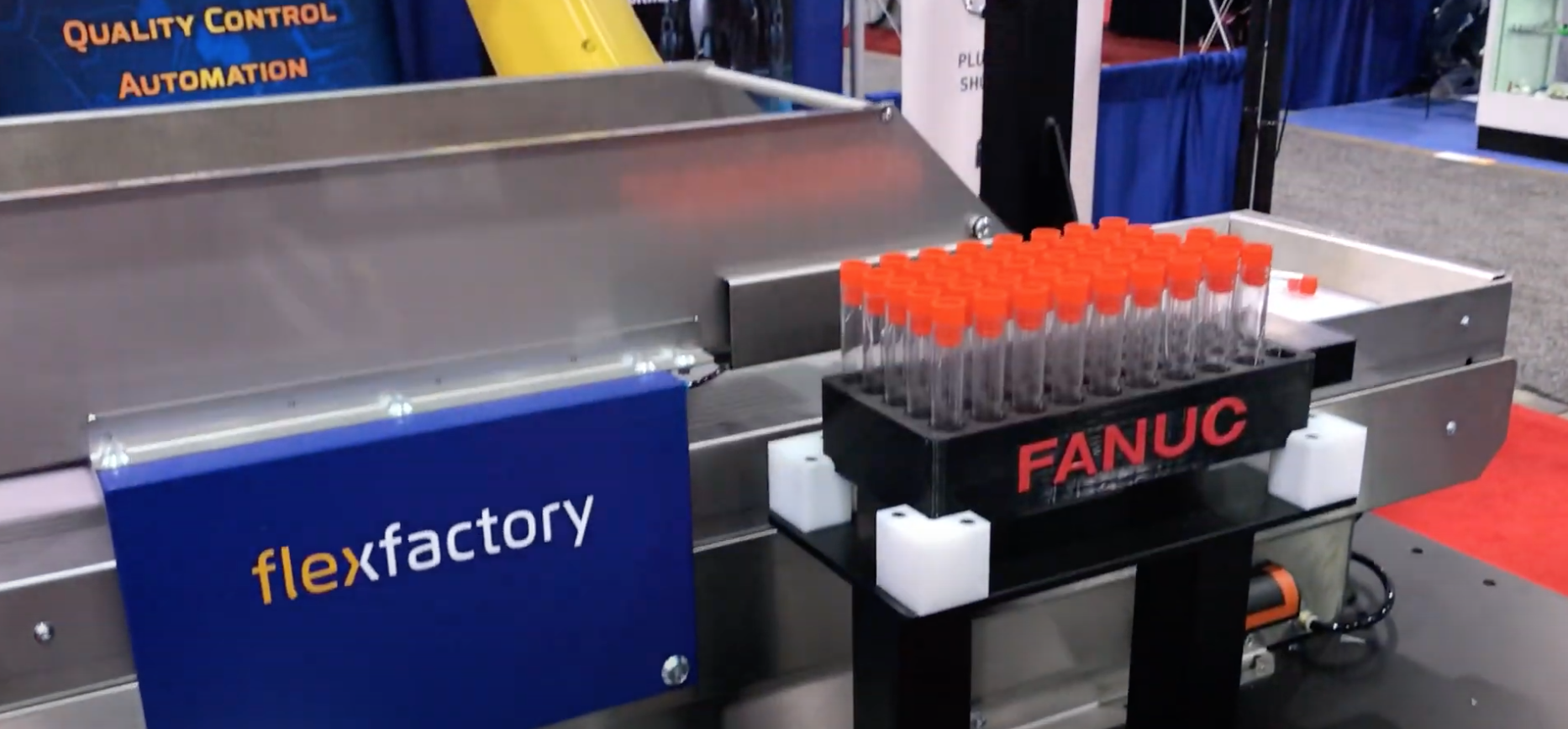
- What brand and type of robot? Delta robots, such as ABB, Fanuc or Yaskawa, have the fastest cycle time, but are best for moving parts from one belt feeder to another with minimal vertical motion and relatively low payload parts. SCARA and 6-Axis robots are best for flexible feeders. SCARA, such as Denso, Epson, Fanuc, and Omron are a little faster due to lower mass and fewer axes to manipulate. But if the part must be picked or placed at an angle other than parallel to the feed deck it will require the motion of a 6-axis robot such as ABB, Denso, Fanuc, Kuka, Motoman or UR
- What software configuration tools are available to match the robot controller of the selected brand with the machine vision system and feeder? If these interfaces are pre-designed, it will shorten the development task, reduce engineering cost and speed up the time required to deploy the system
- How is the robot and feeder mounted? Preferably a solid, welded steel base is available so that the platform for the separate components are stable. Motion or vibration between the vision system, feed deck and robot will cause picking and placing errors. The frame and enclosure should be tall enough to mount the vision system the required distance from the feed deck so that the FOV is as wide as the feed deck. This might require a 48″ / 1200mm height over the level of the feed deck. So the safety enclosure, if there is one, should be sized at 84″ tall for a 36″ base height
- What technical support is available from the system provider to assure an excellent experience with the automation task?
- Evaluation of parts prior to system quotation?
- After-sale phone support?
- Customer training?
- Before and after commissioning field support?

Recent Comments