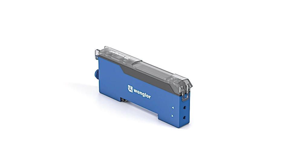
P1XD131 Fiber-optic amplifier
Fiber-Optic Amplifier
Applications: Sensors & I/O
Description
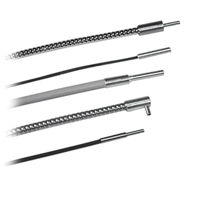
Fiber-optic sensors work according to the energetic principle in which light is emitted via one fiber-optic cable and received via another. The amplifier can be adapted to a wide range of application requirements through the use of flexible plastic fiber-optic cables or glass fiber-optic cables with adapter no. 7. The display shows both the switching threshold and the currently received signal, which means that the sensor can be set up intuitively and quickly using the buttons. More complex parameterizations can be conveniently carried out via the wenglor weCon app on a mobile device or via IO-Link. All sensor information is also provided via the IO-Link process data. Both the fiber-optic cable and the amplifier can be mounted without tools, which further simplifies handling.
Features at a Glance
- Tool-free assembly
- Intuitive setup using display
- NFC communication via the weCon app and IO-Link
- LED blue light
Technical Data
Optical Data
| Switching Hysteresis | < 15 % |
| Light Source | Blue Light |
| Wavelength | 455 nm |
| Service Life (T = +25 °C) | > 100,000 h |
| Max. Ambient Light | 10,000 Lux |
Electrical Data
| Supply Voltage | 10 … 30 V DC |
| Supply Voltage with IO-Link | 18 … 30 V DC |
| Current Consumption (Ub = 24 V) | < 40 mA |
| Switching Frequency | 7 kHz |
| Response Time | 71 µs |
| On-/Off-Delay | 0 … 10,000 ms |
| Temperature Drift | < 10 % |
| Temperature Range | -25 … 60 °C |
| Switching Output Voltage Drop | < 2 V |
| Switching Output/Switching Current | 100 mA |
| Short Circuit Protection | yes |
| Reverse Polarity Protection | yes |
| Overload Protection | yes |
| Teach Mode | NT, MT, MT with dynamic readjustment, jump detection, DT, BT, WT |
| IO-Link transmission speed | COM3 |
| Interface | IO-Link V1.1.3 |
| Protection Class | III |
Mechanical Data
| Setting Method | NFC Display |
| Housing Material | Plastic, ABS Plastic, PC Plastic, PA |
| Degree of Protection | IP50 |
| Connection | M8 × 1; 4-pin |
| DIN-Rail mounting | 35 mm |
| Weight | 35 g |
Safety-relevant Data
| MTTFd (EN ISO 13849-1) | 640.47 a |
General Data
| Scope of delivery | 1 × initial start-up instructions 1 × sensor |
Output
| IO-Link | yes |
| NPN NC, NPN NO | yes |
Adjustable parameters
| Output | Push-pull NPN PNP |
| Circuit | inactive Error output NC NC+NO NO |
| Other parameters | 2 switching points Off-delay On-delay Dynamic readjustment Error indicator Error output Filter Hysteresis Switching point Emitted light Sensor localization Adjustable sensor mode Teach mode |
Standards and certificates
       |
Connection Diagram
 |

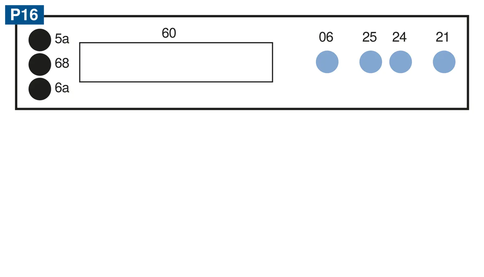
Ctrl. Panel
|
06 = Teach Button
21 = Mode Button 24 = Plus Button 25 = Minus Button 5a = Switching Status Indicator, O1 60 = display 68 = Power LED 6a = Switching Status Indicator, O2 |
Complementary Products
|