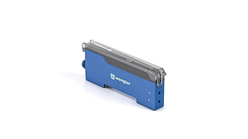
P1XD012 Fiber-optic amplifier
Fiber-Optic Amplifier
In Stock
$192.00
per unit
Applications: Sensors & I/O
Description
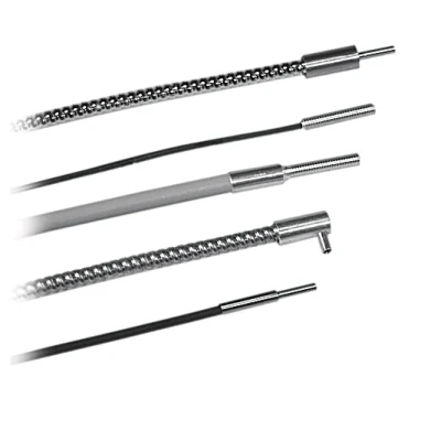
Fiber-optic sensors work according to the energetic principle in which light is emitted via one fiber-optic cable and received via another. The amplifier can be adapted to a wide range of application requirements through the use of flexible plastic fiber-optic cables or glass fiber-optic cables with adapter no. 7. The switching point can be easily adjusted using the potentiometer. Both the fiber-optic cable and the sensor can be mounted without tools, which further simplifies handling.
Features at a Glance
- Tool-free assembly
- Can be adjusted using potentiometers
- IO-Link 1.1
- Diverse usage options: Barrier, reflex, reflex light barrier
Technical Data
Optical Data
| Switching Hysteresis | < 15 % |
| Light Source | Red Light |
| Wavelength | 633 nm |
| Service Life (T = +25 °C) | > 100,000 h |
| Max. Ambient Light | 10,000 Lux |
Electrical Data
| Supply Voltage | 10 … 30 V DC |
| Supply Voltage with IO-Link | 18 … 30 V DC |
| Current Consumption (Ub = 24 V) | < 30 mA |
| Switching Frequency | 0.9 kHz |
| Switching frequency (speed mode) | 1.8 kHz |
| Response Time | 263 µs |
| On-/Off-Delay | 0 … 200 ms |
| Temperature Drift | < 10 % |
| Temperature Range | -25 … 60 °C |
| Switching Output Voltage Drop | < 2 V |
| Switching Output/Switching Current | 100 mA |
| Short Circuit Protection | yes |
| Reverse Polarity Protection | yes |
| Overload Protection | yes |
| IO-Link transmission speed | COM2 |
| Interface | IO-Link V1.1 |
| Protection Class | III |
Mechanical Data
| Setting Method | Potentiometer |
| Housing Material | Plastic, ABS Plastic, PC Plastic, PA |
| Degree of Protection | IP50 |
| Connection | M8 × 1; 4-pin |
| DIN-Rail mounting | 35 mm |
| Weight | 33 g |
Safety-relevant Data
| MTTFd (EN ISO 13849-1) | 640.47 a |
General Data
| Scope of delivery | 1 × initial start-up instructions 1 × sensor |
Output
| IO-Link | yes |
| NPN NO | yes |
Adjustable parameters
| Output | Push-pull NPN PNP |
| Circuit | Error output inactive NC+NO |
Standards and certificates
      |
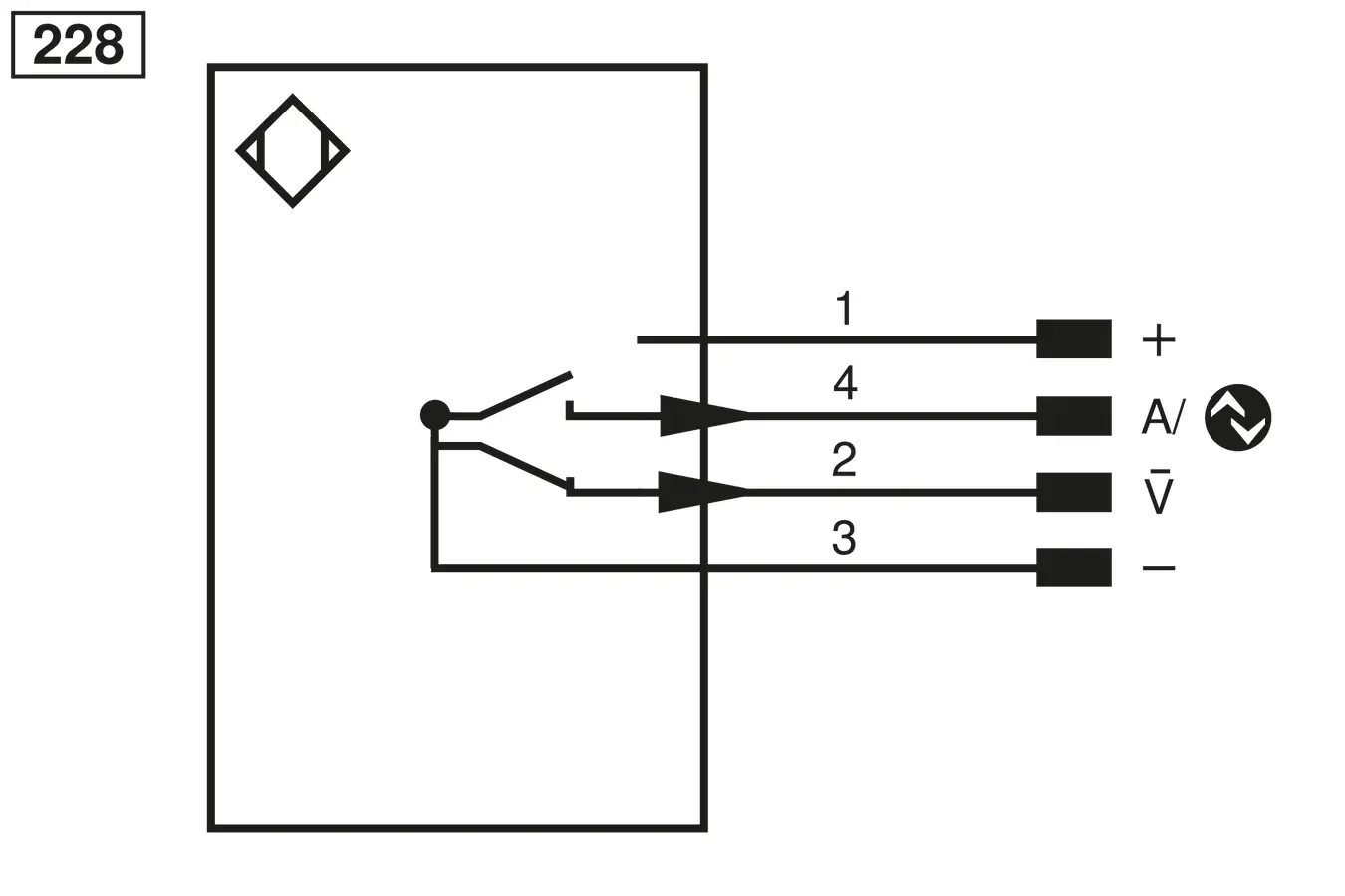
Connection Diagram
 |
Ctrl. Panel
|
05 = Switching Distance Adjuster
5a = Switching Status Indicator, O1 68 = Power LED |

Complementary Products
|