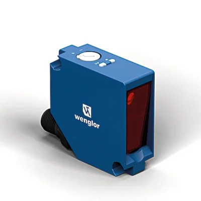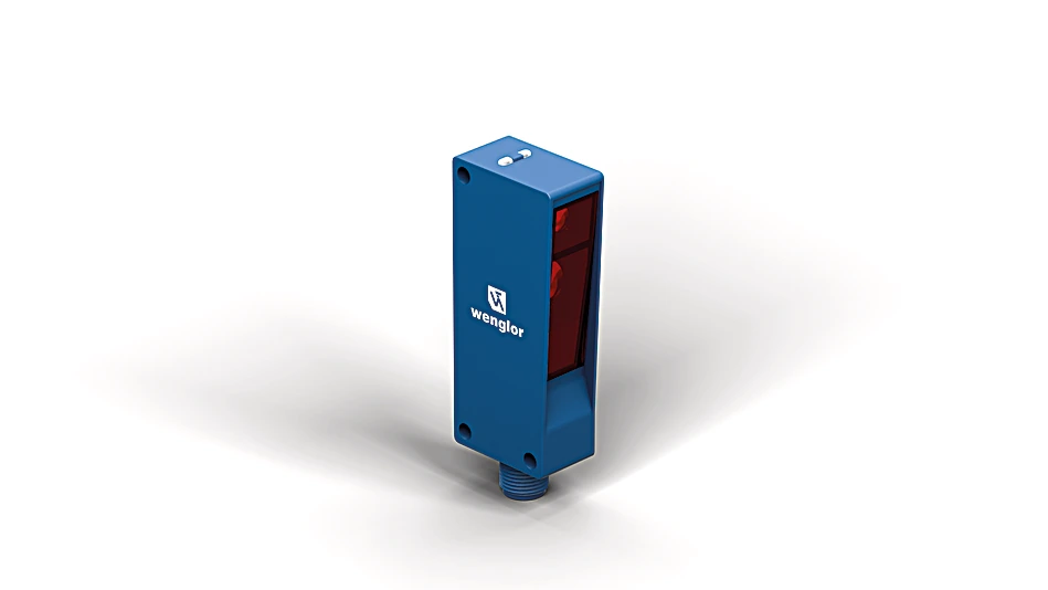
P1NH801 Reflex Sensor with Background Suppression
Reflex Sensor
In Stock
$565.00
per unit
Applications: Sensors & I/O
Description
The reflex sensor with background suppression works with laser light according to the angle measurement principle and is designed to detect objects against any background. The sensor always has the same switching distance, regardless of the color, shape and surface of the objects. Thanks to the fine laser beam, even small parts can be reliably detected. The IO-Link interface can be used to configure reflex sensors (PNP/NPN, NC/NO) and to output switching statuses.
Features at a Glance
- Condition monitoring
- IO-Link 1.1
- Laser class 1
- Collimated laser light beam
Technical Data
Optical Data
| Range | 400 mm |
| Setting Range | 65 … 400 mm |
| Switching Hysteresis | < 1 % |
| Light Source | Laser (red) |
| Wavelength | 655 nm |
| Service Life (T = +25 °C) | 100,000 h |
| Laser Class (EN 60825-1) | 1 |
| Max. Ambient Light | 10,000 Lux |
| Light Spot Diameter | see Table 1 |
Electrical Data
| Supply Voltage | 10 … 30 V DC |
| Supply Voltage with IO-Link | 18 … 30 V DC |
| Current Consumption (Ub = 24 V) | < 15 mA |
| Switching Frequency | 600 Hz |
| Switching Frequency (interference-free mode) | 300 Hz |
| Response time (interference-free mode) | 1.7 ms |
| Response Time | 0.83 ms |
| Temperature Drift | < 2 % |
| Temperature Range | -25 … 60 °C |
| Switching Output Voltage Drop | < 2 V |
| Switching Output/Switching Current | 100 mA |
| Short Circuit Protection | yes |
| Reverse Polarity Protection | yes |
| Overload Protection | yes |
| Interface | IO-Link V1.1 |
| Protection Class | III |
Mechanical Data
| Setting Method | Single-turn |
| Housing Material | Plastic, ABS/PC |
| Degree of Protection | IP67 IP68 |
| Connection | M12 × 1; 4-pin |
| Optic Cover | Plastic, PMMA |
| Weight | 29 g |
Safety-relevant Data
| MTTFd (EN ISO 13849-1) | 2,096.76 a |
General Data
| Scope of delivery | 1 × initial start-up instructions 1 × sensor |
Output
| NPN NC, NPN NO | yes |
| IO-Link | yes |
Adjustable parameters
| Output | Push-pull NPN PNP |
| Circuit | NC NO inactive Error output NC+NO |
| Other parameters | Off-delay On-delay Mode of operation Hysteresis Switching point Emitted light |
| All other parameters can be found in the product documentation. |
Standards and certificates
       |
Table 1
| Detection Range | 60 mm | 200 mm | 400 mm |
| Light Spot Diameter | 3 mm | 3 mm | 3 mm |
Connection Diagram
 |

Ctrl. Panel
|
05 = Switching Distance Adjuster
30 = Switching Status/Contamination Warning 68 = Power LED |

Complementary Products
|