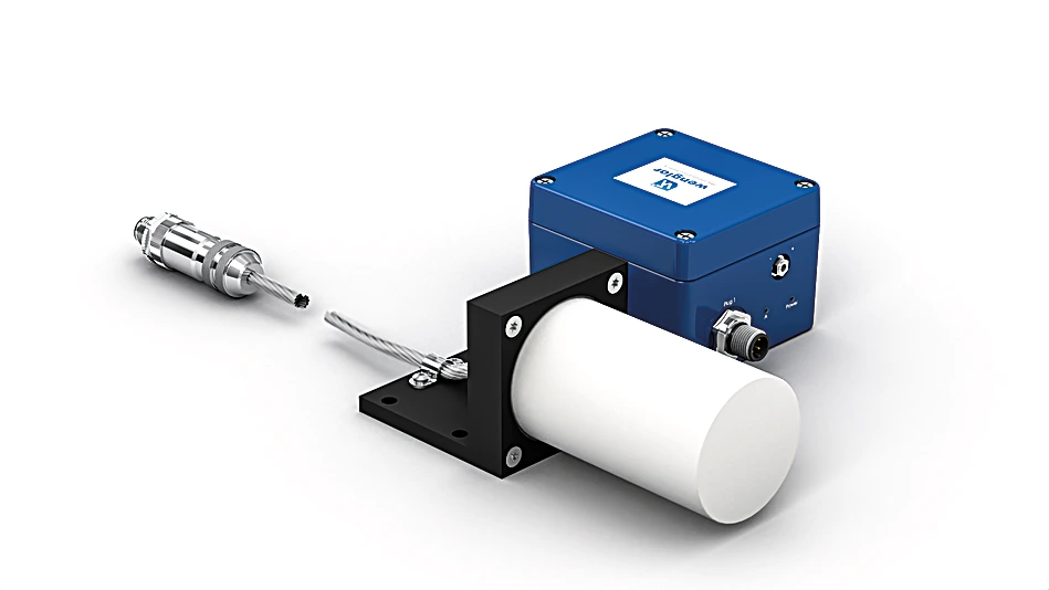
INRT011 Inductive Sensor for Extreme Temperature Ranges
Inductive Sensor
In Stock
$5,397.23
per unit
Applications: Sensors & I/O
Description
The sensors consist of a sensor head and an analysis module, and are laid out for use in very hot work environments. Together with unparalleled service life in hot surroundings, large switching distances assure maximum system availability. Easily interchangeable sensor heads with numerous standard cable lengths are additionally available as separate replacement parts.Switching distance can be quickly adjusted via a potentiometer within a temperature range of -60 to 450° C. This product has been discontinued, but is still available as a spare part. Successor
Features at a Glance
- Large temperature range from -60 to 450° C
- Long service life of up to 100 000 hours
- Quickly interchangeable sensor head
Technical Data
Inductive Data
| Switching Distance | 25 mm |
| Correction Factors Stainless Steel V2A/CuZn/Al | 1,27/1,29/1,33 |
| Mounting | Non-flush |
| Mounting A/B/C/D in mm | 95/200/40/85 |
| Switching Hysteresis | < 10 % |
Electrical Data
| Supply Voltage | 18 … 30 V DC |
| Current Consumption (Ub = 24 V) | < 70 mA |
| Switching Frequency | 200 Hz |
| Sensor head temperature range | -60 … 450 °C |
| Analysis module temperature range | 0 … 50 °C |
| Number of Switching Outputs | 2 |
| Switching Output Voltage Drop | < 3.5 V |
| Switching Output/Switching Current | 50 mA |
| Residual Current Switching Output | < 10 mA |
| Short Circuit Protection | yes |
| Reverse Polarity Protection | yes |
| Overload Protection | yes |
| Protection Class | III |
| Service Life | 100,000 h |
Mechanical Data
| Sensing face | Ceramic |
| Sensor head material | Aluminum, anodised |
| Analysis module material | Aluminum, powder-coated |
| Degree of protection, sensor head | IP60 |
| Degree of protection, analysis module | IP67 |
| Connection | M12 × 1; 4-pin |
| Cable length (L) | 20 m |
| Cable Jacket Material | Stainless steel, V2A (1.4301 / 304) |
| Outer diameter cable | 6.6 mm |
| PWIS-free | yes |
| Weight | 2,600 g |
General Data
| Scope of delivery | 1 × sensor |
Output
| PNP NC, PNP NO | yes |
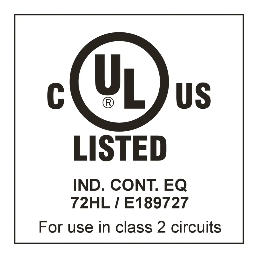
Standards and certificates
     |
Connection Diagram
 |

Ctrl. Panel
|
01 = Switching Status Indicator
05 = Switching Distance Adjuster 68 = Power LED |