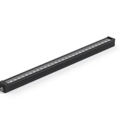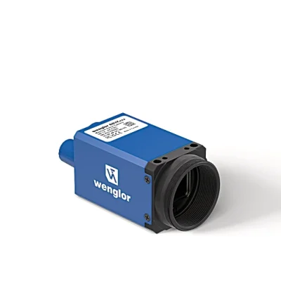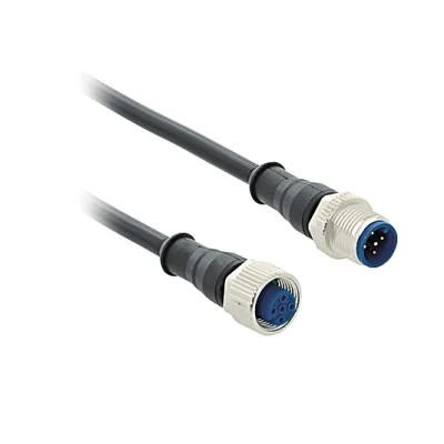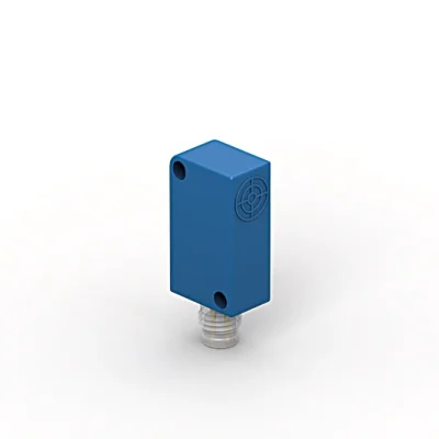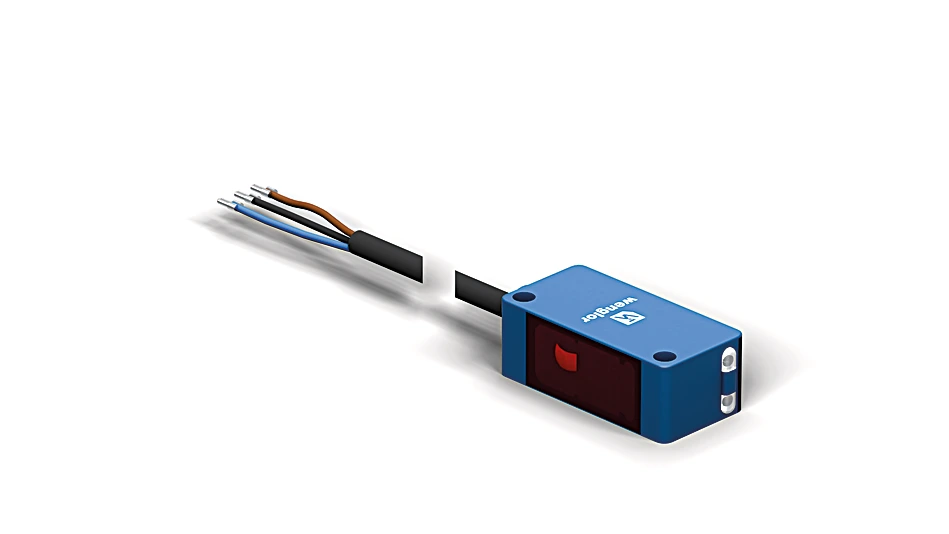
P1KE001S01 Through-Beam Sensor
Through-Beam Sensor
In Stock
$200.00
per unit
Applications: Sensors & I/O
Description
The through-beam sensor works with red light as well as a transmitter and a receiver. Thanks to their high light intensity, the sensor provides a high degree of operational reliability even with interferences like steam, fog or dust. The transmitter can be deactivated using test input in order to test the functionality of the through-beam sensor. The IO-Link interface can be used to configure the sensor (PNP/NPN, NC/NO, switching distance), as well as for reading out switching statuses and signal values.
Features at a Glance
- Condition monitoring
- High light intensity with large switching reserve
- IO-Link 1.1
- Test input for high operational reliability
Technical Data
Optical Data
| Range | 6,000 mm |
| Smallest Recognizable Part | see Table 1 |
| Switching Hysteresis | 10 % |
| Light Source | Red Light |
| Service Life (T = +25 °C) | 100,000 h |
| Max. Ambient Light | 10,000 Lux |
Electrical Data
| Sensor Type | Receiver |
| Supply Voltage | 10 … 30 V DC |
| Supply Voltage with IO-Link | 18 … 30 V DC |
| Current Consumption (Ub = 24 V) | < 20 mA |
| Switching Frequency | 1,000 Hz |
| Switching Frequency (interference-free mode) | 500 Hz |
| Response Time | 0.5 ms |
| Response time (interference-free mode) | 1 ms |
| Temperature Drift | < 10 % |
| Temperature Range | -40 … 60 °C |
| Switching Output Voltage Drop | < 2 V |
| Switching Output/Switching Current | 100 mA |
| Residual Current Switching Output | < 50 µA |
| Short Circuit Protection | yes |
| Reverse Polarity Protection | yes |
| Overload Protection | yes |
| Lockable | yes |
| Interface | IO-Link V1.1 |
| Protection Class | III |
Mechanical Data
| Setting Method | Potentiometer |
| Housing Material | Plastic, ABS/PC |
| Degree of Protection | IP67 IP68 |
| Connection | Cable; 3-wire |
| Cable length (L) | 2 m |
| Cable Jacket Material | PVC |
| Wire cross-section | 0.14 mm² |
| Optic Cover | Plastic, PMMA |
| Weight | 47 g |
Safety-relevant Data
| MTTFd (EN ISO 13849-1) | 2,111.25 a |
General Data
| Scope of delivery | 1 × BEF-SET-01 mounting set 1 × initial start-up instructions 1 × sensor |
Output
| PNP NO | yes |
| IO-Link | yes |
Adjustable parameters
| Output | Push-pull NPN PNP |
| Circuit | NC/NO NC NO |
| Other parameters | Off-delay On-delay Mode of operation Hysteresis Switching point |
| All other parameters can be found in the product documentation. |
Standards and certificates
      |
Table 1
| Distance transmitter/receiver | 1 m | 2 m | 6 m |
| Smallest Recognizable Part | 4 mm | 1 mm | 1 mm |
Connection Diagram
 |

Ctrl. Panel
|
30 = Switching Status/Contamination Warning
68 = Power LED |

Complementary Products
|