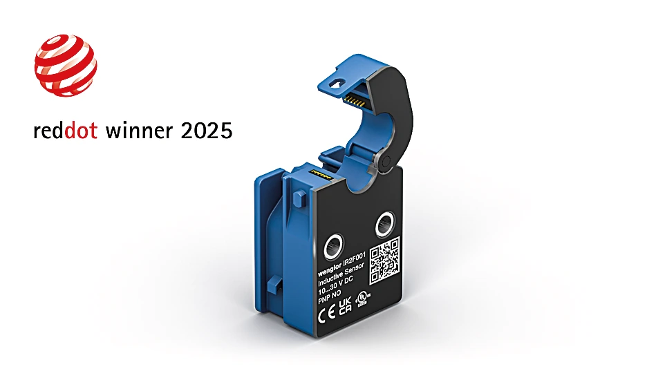
IR2F001 Inductive Sensor Ring sensor
Inductive Ring Sensor
In Stock
$341.00
per unit
Applications: Sensors & I/O
Description
The inductive ring sensor with separable housing enables quick and flexible mounting on various objects, such as hoses. Its compact construction, with a switching status indicator visible on all sides and a cable outlet in the hose direction, is particularly well suited for confined spaces. It is intuitive to operate via the potentiometer or the IO-Link interface. The sensor switches independently of the material thanks to correction factor 1. Frequency switching enables the operation of several sensors in the immediate vicinity without mutual interference.
Features at a Glance
- Flexible soft binder on the sensor
- Intuitive operating concept with IO-Link interface
- Correction factor 1
- Plug and Play
- Separable housing
Technical Data
Inductive Data
| Inside diameter | 10.2 mm |
| Max. tube diameter | 10 mm |
| Installation A/Bx/By/C in mm | 0/15/35/5 |
| Installation A/Bx/By/C in mm with frequency switching | 0/0/0/5 |
| Functional principle | Static |
| Smallest recognizable object (Ø) | 2.5 mm* |
| Correction Factors Stainless Steel V2A/CuZn/Al | 1/1/1 |
Electrical Data
| Supply Voltage | 10 … 30 V DC |
| Current Consumption (Ub = 24 V) | < 20 mA |
| Object speed | < 50 m/s |
| Response Time | < 300 µs |
| Ready-state delay | < 1.5 s |
| Switching Output Voltage Drop | 1.5 V |
| Temperature Range | 0 … 60 °C |
| Short Circuit Protection | yes |
| Overload Protection | yes |
| Reverse Polarity Protection | yes |
| Switching Output/Switching Current | 100 mA |
| Pulse extension | 200 ms |
| Interface | IO-Link V1.1 |
| IO-Link Version | 1.1 |
Mechanical Data
| Connection | M8 × 1; 4-pin |
| Setting Method | Potentiometer/IO-Link |
| Housing Material | Plastic, PA |
| Hanger opening/closing cycles | Max. 100 |
| Degree of Protection | IP54 |
| Weight | 26 g |
Safety-relevant Data
| MTTFd (EN ISO 13849-1) | 1,018.99 a |
General Data
| Scope of delivery | 1 × sensor 1 × ZR0E001 soft binder |
| Packaging unit | 1 Piece |
Output
| PNP NO | yes |
Adjustable parameters
| Output | PNP Push-pull NPN |
| Circuit | NO NC NC/NO |
| Pulse extension | 5 … 200 ms |
| Other parameters | Sensitivity Error indicator Frequency switching |
| All other parameters can be found in the product documentation. |
Standards and certificates
      |
Connection Diagram
 |

Ctrl. Panel
|
17 = Sensitivity Adjustment
1c = Status display/setup aid 3a = Switching Status Indicator/Error Indicator 68 = Power LED 0b = Pulse length adjuster / for IRxF: additional calibration mode |